I know the specific anxiety that comes with sourcing parts for older machinery. You have a customer who needs a replacement yesterday, but the OEM 1 stopped manufacturing that specific track shoe years ago. You are left staring at a rusty, worn-out sample on your desk, worrying that without a blueprint, you have hit a dead end. Rest assured, you haven't.
The answer is a definitive yes. At Dingtai, we can successfully reverse-engineer a complete track shoe assembly directly from your physical sample. By combining industrial-grade 3D laser scanning to capture the geometry and optical emission spectrometry to identify the material composition, we can generate precise manufacturing drawings and produce high-quality replicas without ever needing the original prints.
This scenario is actually quite common in our line of work. Many of our partners in the United States and Europe come to us with nothing more than a used component and a request for stability. We do not require you to be a draftsman or an engineer; we just need you to get the sample to us. Once it arrives at our facility in Fujian, we treat it as the "seed" from which we grow a standardized, mass-producible product line for you.
What is your (Dingtai's) process for reverse-engineering (e.g., 3D scanning, material analysis)?
If the term "reverse engineering" sounds overly technical or risky, let me demystify it for you. It is simply a structured, scientific method of working backward from a finished object to its design intent 2. It is part of our daily routine here at the factory.
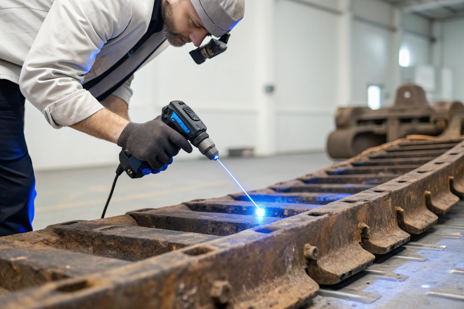
Our process is rigorous and systematic: First, we sandblast the sample to remove contaminants. Then, we use a high-precision 3D laser scanner to generate a digital point cloud of the shape. Simultaneously, we perform destructive lab testing to determine the exact steel alloy and heat treatment depth.
To understand why this is safe and reliable, we need to dive into the engineering details. It is not enough to just measure the length and width with calipers; we have to understand the part's "DNA."
The Journey from Physical to Digital
When your sample arrives, the first step is preparation. We cannot scan a dirty part. We use shot blasting 3 to strip away layers of paint, rust, and grease. This reveals the raw metal surface. Once clean, we place the part on a rotary table and use a metrology-grade 3D laser scanner. Unlike a simple camera, this device projects laser lines across the surface of the track shoe or link. As the lasers move, cameras capture millions of data points, creating a point cloud 4 accurate to within microns.
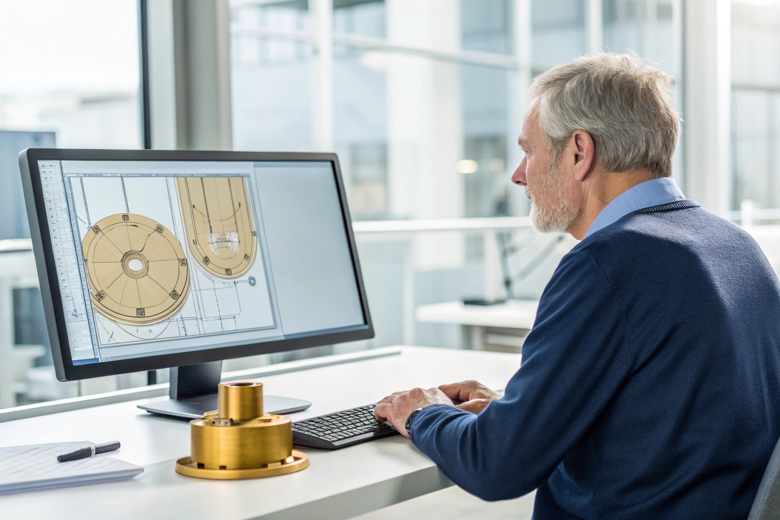
However, a point cloud is just raw data—it is a digital ghost of the object. Our CAD engineers then step in. Using software like SolidWorks or NX, they build a parametric 3D model over the scan data. This is a critical step where human expertise is vital. The scanner sees everything, including surface defects. Our engineers must distinguish between the intended design and the accidental scratches, smoothing out the model to represent what the part looked like before it was used.
Unlocking the Material Secrets
Capturing the shape is only 50% of the job. In the undercarriage business, the material is everything. If we make a track link out of generic mild steel, it will stretch or crack under the weight of a D8 dozer. We have to match the OEM's metallurgical recipe.
We cut a section from your sample and place it in our Optical Emission Spectrometer 5. This machine uses a high-voltage spark to vaporize a tiny bit of the metal. By analyzing the light spectrum emitted, it tells us the exact chemical composition—how much Carbon, Manganese, Boron, and Chromium is in the steel. For example, we might identify it as 35MnB or 40Mn2.
Finally, we look at the heat treatment. We polish a cross-section and view it under a metallographic microscope to see the grain structure. We also use a Rockwell hardness tester to map out the hardness from the surface to the core. This tells us exactly how deep the induction hardening 6 layer is, ensuring your new parts will have the same wear life as the original.
Summary of the Process
| Step | Tool Used | Purpose | Why it matters to you |
|---|---|---|---|
| 1. Cleaning | Shot Blasting Machine | Remove rust/paint | Ensures measurement accuracy |
| 2. Scanning | 3D Laser Scanner | Capture geometry | Guarantees perfect fitment |
| 3. Modeling | CAD Software (NX/SolidWorks) | Create digital blueprint | Allows for mass production |
| 4. Analysis | Spectrometer | Identify Steel Grade | Ensures strength and durability |
| 5. Testing | Hardness Tester | Check Heat Treat | Ensures wear resistance |
How accurate will the final product be compared to the original sample I send?
A common fear I hear from sourcing managers is that a "copied" part will be a "fuzzy" version of the original—loose, ill-fitting, or inconsistent. You worry that the bolt holes won't align or the pitch will be slightly off, causing installation nightmares for your customers.
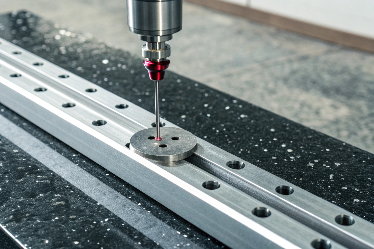
Our scanning precision is within ±0.02mm, and our final manufacturing tolerances are strictly held between ±0.1mm and ±0.3mm depending on the feature. We validate every new mold and first article using a Coordinate Measuring Machine (CMM) to ensure the replacement is often more mathematically perfect than the sample you provided.
It is crucial to distinguish between the accuracy of the measurement and the tolerance of the manufacturing. We control both to ensure the product you receive is premium quality.
The "Design Intent" Correction
When we scan a physical sample, we capture reality, which includes imperfections. Maybe the original casting had a slight flash, or a hole was drilled 0.05mm off-center. We do not blindly copy these errors. Our engineers apply "Design Intent" logic.
For example, if our scanner measures a mounting hole diameter as 20.03mm, we know from engineering standards that the intended design was likely a clean 20.00mm to fit a specific bolt. We correct this in the digital drawing. If we find a bolt circle spacing of 149.92mm, we correct it to the standard 150.00mm. This means the blueprint we generate is often a "perfected" version of the physical sample you sent us. We are restoring the part to its ideal state.
Manufacturing Consistency
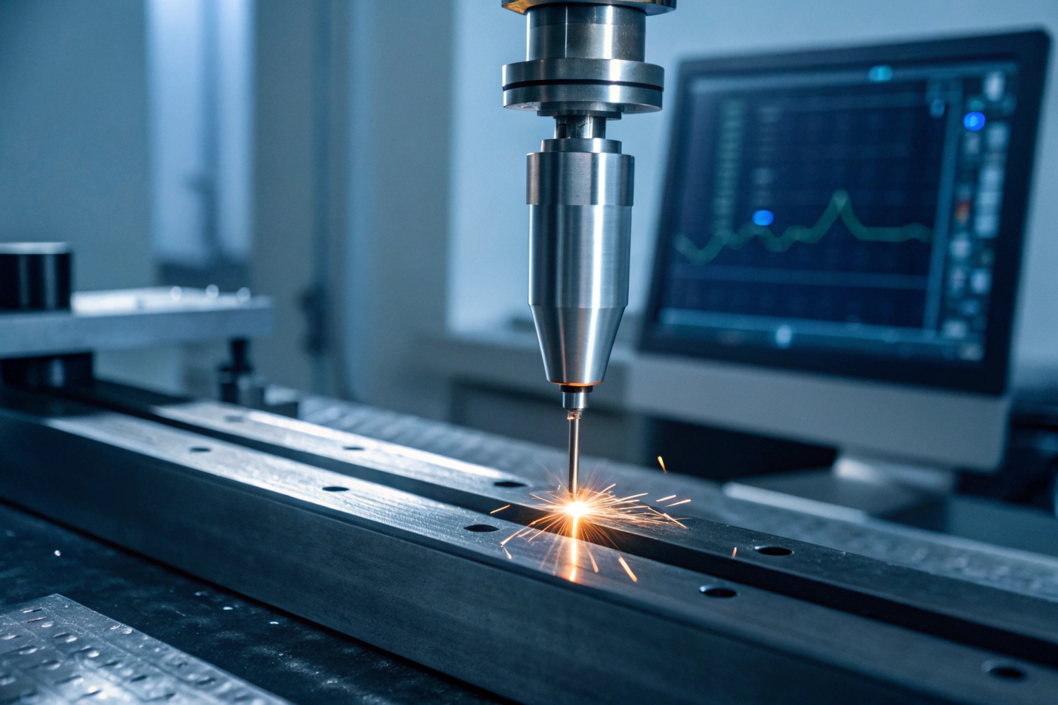
Once the "perfect" drawing is approved by you, we move to production. Whether the part is forged or cast, we apply strict ISO quality controls 7. For critical features—like the pin bores in a track link or the mating surface of a track shoe—we use CNC machining centers 8. CNC machines do not guess; they follow the code to exact coordinates.
To give you peace of mind, before we ship the bulk order, we generate a full dimensional report. We use a Coordinate Measuring Machine 9 to physically touch and measure the key points on the finished product.
Typical Tolerance Standards
Here is a breakdown of the tolerances we adhere to, which meet or exceed standard OEM aftermarket requirements:
| Feature Category | Tolerance Range | Explanation |
|---|---|---|
| Precision Bores (Pin/Bushing) | H7 / g6 (e.g., +0.025 / -0) | Critical for tight interference fits; no wobbling allowed. |
| Mounting Interfaces | ± 0.1mm | Ensures bolts slide in easily without modification. |
| Machined Surfaces | ± 0.2mm | Ensures flat contact with the track chain. |
| Casting/Forging Profile | ± 1.0mm - 1.5mm | Non-functional exterior surfaces; cosmetic standard. |
Do I need to send you a brand-new part, or can you accurately measure my old, worn-out sample?
Finding a brand-new sample of an obsolete part is almost impossible. Usually, the only reference you have is the broken or worn-out piece that just came off the machine in the field. You might hesitate, thinking a worn part is useless for making a new mold.
You do not need to send a new part; a worn-out sample works perfectly fine for us. Our engineers utilize "wear reconstruction" techniques to logically deduce the original dimensions by analyzing non-contact surfaces, symmetry, and industry standards.
This is where experience beats pure technology. A scanner can only see what is there, but an experienced undercarriage engineer knows what used to be there. We have been doing this for over 20 years, so we know how to "read" a worn part.
The Logic of Wear Reconstruction
When a track shoe or link wears down, it does not dissolve evenly like a sugar cube. Wear is directional. It happens where the metal touches the ground or the sprocket.
- Finding the "Zero" Point: We look for surfaces that never experienced friction. The side of a link, the recessed area around a bolt hole, or the inner face of a shoe usually retain the original casting surface. We use these "virgin" surfaces as our reference datum to build the rest of the model.
- Symmetry and Mirroring: Often, wear is uneven. If a dozer was working on a side slope, the left side of the link might be destroyed while the right side is decent. We can scan the good side and "mirror" it in the CAD software to restore the damaged side.
- Standard Component Deduction: We know that a track shoe must fit a specific chain. By measuring the bolt diameter (which is standard) and the nut profile, we can reverse-calculate the exact size of the mounting holes, even if they have been worn into ovals.
Calculating Pitch from a Stretched Chain
The hardest thing to measure on a used sample is the "pitch" (the distance between pins), because internal wear causes the chain to stretch or "elongate." If you measure a used link, the pitch might read 205mm, but the original was likely 203mm.
We solve this by measuring the wall thickness of the bushing bore and the pin diameter. We also reference standard industry pitch tables. The heavy machinery industry uses standardized pitches (e.g., 135mm, 154mm, 171mm, 190mm, 203mm, 216mm). If our measurement comes close to one of these numbers, we can confidently snap the design to the correct standard pitch.
How We Handle Specific Wear Types
| Wear Problem | Our Solution Strategy | Reliability |
|---|---|---|
| Worn Grouser (Cleat) Height | We restore height based on the machine's tonnage standard (e.g., 50mm for 20-ton class). | High |
| Elongated / Oval Bolt Holes | We locate the center based on the bolt circle diameter from non-worn areas. | Very High |
| Thinned Rail Surface | We add material back to match the standard link height for that chassis size. | High |
So, please do not worry about the condition of your sample. As long as it is not broken into tiny unrecognizable fragments, we can usually work with it.
How long does this entire reverse-engineering and first-sample process take?
Time is the enemy in the parts business. When you are out of stock, you are losing sales, and you need a clear timeline to give your customer. You need to know if this is a two-week project or a six-month ordeal.
Generally, the entire process from receiving your sample to shipping the first approved article takes about 6 to 8 weeks. This includes 3-5 days for engineering and design, 30-45 days for mold manufacturing and trial production, followed by final inspection and shipping.

We believe in being upfront about lead times so you can plan your inventory. Let's break down exactly where the time goes in this timeline.
Phase 1: Data to Design (Week 1)
As soon as your package arrives at our factory, the clock starts.
- Day 1-2: Cleaning, scanning, and material lab testing.
- Day 3-5: Our engineers create the 3D model and generate the 2D technical drawing.
- Your Role: We will email you the PDF drawing at the end of this week. We need your confirmation on key dimensions (like bolt hole spacing) to proceed. The faster you approve, the faster we move.
Phase 2: Tooling Creation (Weeks 2-6)
This is the most time-consuming part, but it cannot be rushed. We are building the high-strength steel molds (for forging) or aluminum patterns (for casting) that will produce your parts for years to come.
- CNC Machining: We cut the mold shape.
- Flow Simulation: We verify that molten metal will flow correctly into the mold without creating air pockets.
- Trial Shots: We produce the very first raw pieces to check the mold function.
Phase 3: Validation and First Article (Week 7)
We do not just ship the first thing that comes out of the mold. We produce a small batch of "First Article" samples.
- Destructive Test: We sacrifice one sample, cutting it open to check for internal defects like porosity.
- Dimensional Check: We measure the sample against the drawing we created in Week 1.
Phase 4: Logistics (Week 8)
Once the sample passes our internal QC, we ship it to you. We typically use air courier services (DHL or FedEx) for samples, so they arrive at your office in the US within 3-5 days. Once you hold the part and give us the green light, we lock the mold design and are ready for immediate mass production.
Options to Accelerate
If you are in a desperate situation, we do have some levers we can pull:
- 3D Printed Sand Molds: For casting parts, we can 3D print the sand mold 10 directly. This skips the 4-week tooling process for the hard pattern. It is more expensive per unit, but we can get you a sample in 2 weeks instead of 6.
- Priority Tooling: We can assign double shifts to our mold-making team to shave off about 10 days from the tooling phase.
Conclusion
Reverse engineering is the ultimate solution when the supply chain for older machines dries up. It bridges the gap between a worn-out past and a profitable future. At Dingtai, we turn your physical problem into a digital asset and then into a tangible, high-quality product. You supply the sample; we supply the engineering precision, material science, and manufacturing power. Send us that old part, and let’s get your inventory moving again.
Footnotes
1. Definition of Original Equipment Manufacturer (OEM) in supply chains. ↩︎
2. Understanding how design intent works in reverse engineering. ↩︎
3. Overview of shot blasting for surface preparation and cleaning. ↩︎
4. Explanation of point cloud data in 3D scanning. ↩︎
5. How optical emission spectrometry analyzes metal chemical composition. ↩︎
6. Benefits of induction hardening for increasing metal wear resistance. ↩︎
7. Summary of ISO quality management standards for manufacturing. ↩︎
8. Introduction to CNC machining processes and technology. ↩︎
9. How Coordinate Measuring Machines (CMM) ensure dimensional accuracy. ↩︎
10. Case studies on rapid prototyping using 3D printed molds. ↩︎